Computer Networking
A blog of all the things i learnt about the computer networing.
INTRODUCTION#
what is internet?
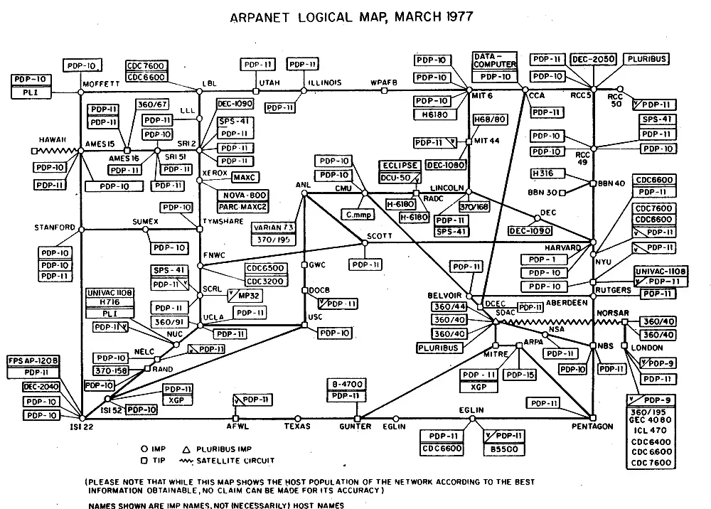
ans) a network of billions of computing devices called hosts and end systems. The internet grew out of ARPANET in 1970s. the data connection is the internet the wires the routers the switches etc. ARPANET approced tcp/ip in 1983 (birthdate of modern internet)
what is web?
it is the worldwide network of interconnected hyper text pages. web is the application of internet and the dns. this was invernted by CERN.
Apart form web there are other applications of internet also such as email,ssh, bitTorrent,voice-over-ip telepony, FTP , remote Desktop etc.
who controlls int internet?
ICANN (Internet Corporation for Assigned Names and Numbers) assing ip addresses. operates 13 root dns servers IETF ((Internet Engineering Task Force) develops protocol of how the devices interact
Internet is distributed and loosely coupled. A network protocol defines proper communication pattern between devices.
Packet switching vs circuit switching
Circuit switching establishes a dedicated communication path between devices before data transfer begins. This path remains exclusively reserved until the session ends where as Packet switching breaks data into small chunks (packets) that travel independently through the network.
Switching here means the way link is shared by competing users.
Throughput :- it is the rate of data transfer. Latency :- It is the delay of an action.
Packet switching#
Packet switching breaks data into small chunks (packets) that travel independently through the network.
- Data is divided into packets with addressing information
- No pre-established path exists; packets find their own way
- Network resources are shared dynamically among all users
- Receiving end reassembles packets into the original data
- Example: When streaming videos online, data travels as thousands of independent packets
The internet was designed to be best effort delivery system and hence no effort was made to implement confirmation that the some packet is dropped. we overcame this using protocols such as tcp.
souces of packet delay#
- transmission
- processing
- queue
- propagation
peering link and internet exchange point#
a visualization of the cabes around the world ↗
Packets and layers in the internet#
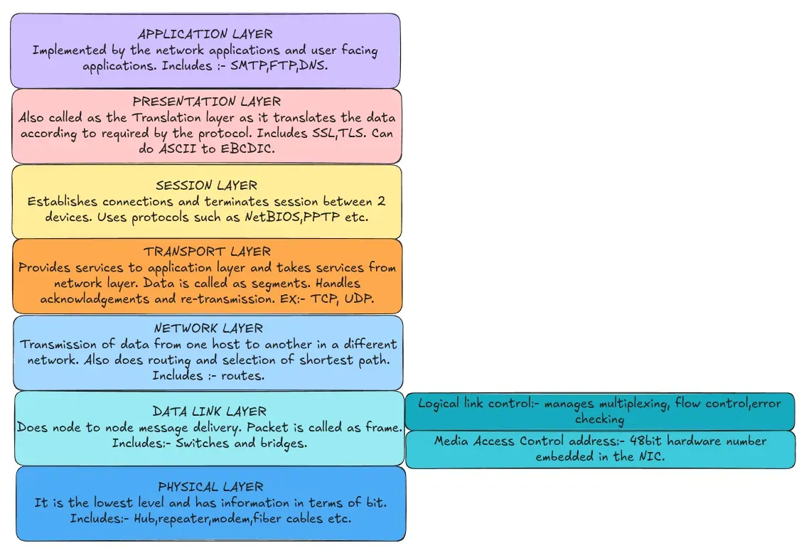
There are a lot of differnt layers and protocols which basically serve as an abstraction.
Layers add additonal header bytes to the packets. These layers are designed on the basis of popular software engineering pattern called separation of concerns.
sockets#
these are at a high level the connection medium for the computer to talk to the web. we just have to specify which port to connect and which ip and each TCP UDP packet has a unique 16 bit port number. The OS manages ports and only one process may listen on a given port. This is also how the different tabs on same browser get the correct reponse even though the whole ip is same on one pc.
Sockets are also viewed as a software abstraction of a network connection.
Application laeyer protocol#
Peer-to-peer architecture#
Napster technically built p2p
HTTP#
HTTP is the foundation of data communication on the World Wide Web, enabling the transfer of hypertext documents between clients and servers. It’s an application layer protocol that forms the basis for web browsing, APIs, and many other internet services.
HTTP transaction/flow steps#
- URL parsing
- DNS Resolution
- TCP Connection establishment
- HTTP Request Construction
- Request Example
- Server Processing
- HTTP Response Construction
- Response processing by browser
- Content Handling by the browser
- Connection is closed or kept alive depending upon the use-case
SMTP#
It is Simple mail transfer protocol and uses port 25 to send and recieve emails.Below is an example smtp connection and conversation
sender’s side
$ telnet mail.example.com 25
Trying 192.168.1.100...
Connected to mail.example.com.
Escape character is '^]'.
220 mail.example.com ESMTP Postfix

EHLO client.example.org
250-mail.example.com
250-PIPELINING
250-SIZE 10240000
250-VRFY
250-ETRN
250-STARTTLS
250-AUTH PLAIN LOGIN
250-AUTH=PLAIN LOGIN
250-ENHANCEDSTATUSCODES
250-8BITMIME
250 DSN

MAIL FROM:<alice@example.org>
250 2.1.0 Ok

RCPT TO:<bob@example.com>
250 2.1.5 Ok

DATA
354 End data with <CR><LF>.<CR><LF>
From: "Alice Smith" <alice@example.org>
To: "Bob Jones" <bob@example.com>
Subject: Project Status Report
Date: Wed, 2 Oct 2025 14:30:22 -0400

Hi Bob,

I've completed the network configuration task we discussed yesterday.
All the routing tables are updated, and the new firewall rules are in place.

Could you please review the changes and confirm if everything looks good?

I've also attached the documentation in our shared folder.

Best regards,
Alice
.
250 2.0.0 Ok: queued as 8F3E92A5B3

QUIT
221 2.0.0 Bye
Connection closed by foreign host.reply
$ telnet mail.example.com 25
Trying 192.168.1.100...
Connected to mail.example.com.
Escape character is '^]'.
220 mail.example.com ESMTP Postfix

EHLO client.example.com
250-mail.example.com
250-PIPELINING
250-SIZE 10240000
250-VRFY
250-ETRN
250-STARTTLS
250-AUTH PLAIN LOGIN
250-AUTH=PLAIN LOGIN
250-ENHANCEDSTATUSCODES
250-8BITMIME
250 DSN

MAIL FROM:<bob@example.com>
250 2.1.0 Ok

RCPT TO:<alice@example.org>
250 2.1.5 Ok

DATA
354 End data with <CR><LF>.<CR><LF>
From: "Bob Jones" <bob@example.com>
To: "Alice Smith" <alice@example.org>
Subject: Re: Project Status Report
Date: Wed, 2 Oct 2025 16:15:45 -0400

Hello Alice,

Thanks for your quick work on this! I've reviewed the changes and everything
looks perfect. The firewall rules are working as expected.

One small suggestion: could we add a rule to allow SSH access from the
development subnet (10.20.30.0/24)?

Otherwise, great job on the documentation too.

Regards,
Bob
.
250 2.0.0 Ok: queued as 9G4F03B6C4

QUIT
221 2.0.0 Bye
Connection closed by foreign host.smtp is also stateful
DNS#
DNS maps host names to IP addresses. Nearby IP addresses are usually physically closer togeater in the network and left-most bits are for usaually the global location and right-most are for local.
Dns hirearchy#
- There are boadly 3 level to the DNS server hirearchy.
- Root DNS servers :- There are 13 root DNS servers maintained by the ICANN around the world. These are the servers where IP addresses of the all top-level-domains are hosted.
- Top Leve Domain (TLD) servers :- These store the IP addresess of the authorative name servers for that domain.
- Authorative Name Servers :- Thse server store the final ip address for the resolution of the request.
DNS Records Types#
- A records - map host names to ip addresses.
- AAAA record - same as A record but for IPv6.
- NS record - list the nameservers for a given domain.
- MX record - list the email servers.
- CNAME record - list the aliases.
- SOA record - store the information about who created these DNS record and how they should be cached.
- SRV record - list server for any generic service.
- TXT record - these are generic key-value storage.
- SPF record - list the outbound mail servers for the domain.
- PTR record - store reverse DNS records, IP address -> hostname.
Round Robin DNS#
Round Robin DNS is a load-balancing technique that distributes network traffic across multiple servers by rotating through a list of IP addresses in response to DNS queries.
How Round Robin DNS Works
-
Multiple A Records: The DNS administrator configures multiple A records (or AAAA for IPv6) with the same hostname but different IP addresses.
-
Rotation Mechanism: When a client requests the IP address for the hostname, the DNS server returns all IP addresses associated with that hostname but rotates the order with each response.
-
Client Connection: The client typically attempts to connect to the first IP address in the list it receives.
Reiable Transport System Across the Internet#
UDP#
UDP is a connectionless, lightweight transport layer protocol that provides a minimal set of services for application-level communication. Unlike TCP, UDP focuses on simplicity and speed rather than reliability and order.
UDP Packet structure

  0      7 8     15 16    23 24    31
+--------+--------+--------+--------+
|     Source      |   Destination   |
|      Port       |      Port       |
+--------+--------+--------+--------+
|     Length      |    Checksum     |
+--------+--------+--------+--------+
|                                   |
|              Payload              |
|                                   |
+-----------------------------------+-
Source Port (16 bits): Optional; identifies the sending application
-
Destination Port (16 bits): Identifies the receiving application
-
Length (16 bits): Length of UDP header and data in bytes
-
Checksum (16 bits): Error detection for header and data
-
Payload: The actual application data
TCP#
TCP is usually implemented by the os. It handles the following:-
Ordering - Data must be chunke by sender and reassembled at the receiver end
Acknowladgement - Delivery of each packet is acknowladged
Pacing - Sender adjusts the packet send rate so that neither reciever nor sender is over loaded
Naive ACK corrctness#
- Do not send n util n-1 is received.
- TImeout is used to decide when a packet needs to be resend.
- It’s called stop and wait method also.
- An acknowladge is always sent by the reciver
Pipelining#
- Mnay packets are sent in parallel.
- Many acknowladges are also sent as pckets are recieved.
- All the packets are needs to be kept as any of them can be lost.
- window size is a mechanism to control pace of network.
- We must handle out of order delivery
- ACK carry a acknowladgement number so sender can know it is for which packet
HOW IS PIPELING IMPLEMENTED#
GO BACK N#
Selective repeat#
demo ↗
max packet number size > half the window size
there is also a problem that if we send to much data over some time in the network (like for example streaming a large movie from the netflix) then there can be case that the sequence number will be reset and for newer packets and sequence number is acknowladged for the okder packets which were already acknowladeged.
TCP#
- TCP requires setting up a connection between two clients before start communication
- In this we choose a set of random initial numbers to start with so that the new connections are not confused with the old packets and connections.
- This way attacker will also have a difficulty in injecting the false packets.
TCP Packet structure#
This is a lot more complex protocol and has lot more headers.
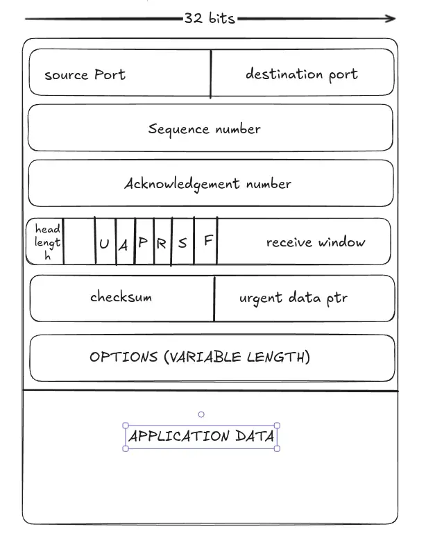
TCP sequence numbers and acknowladgement numbers#
-
sequence numbers :- These incdicate the offset of the byte stream of the segment’s first byte.
-
Cummulative acknowadgements :- these send the next expected sequence numebres (like go back N).
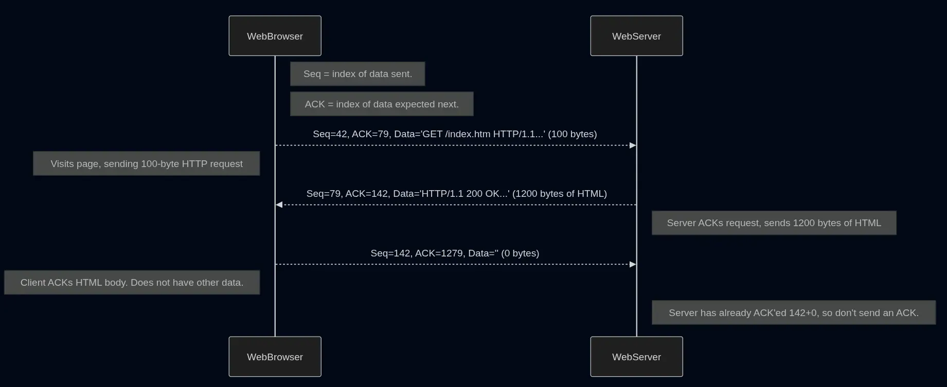 above is a sample exchange of request and response of server and client after handshake
- TImeouts are an important parameter here in tcp. TCP keeps only one timer for the oldetst sgment that is unacknowladeged.
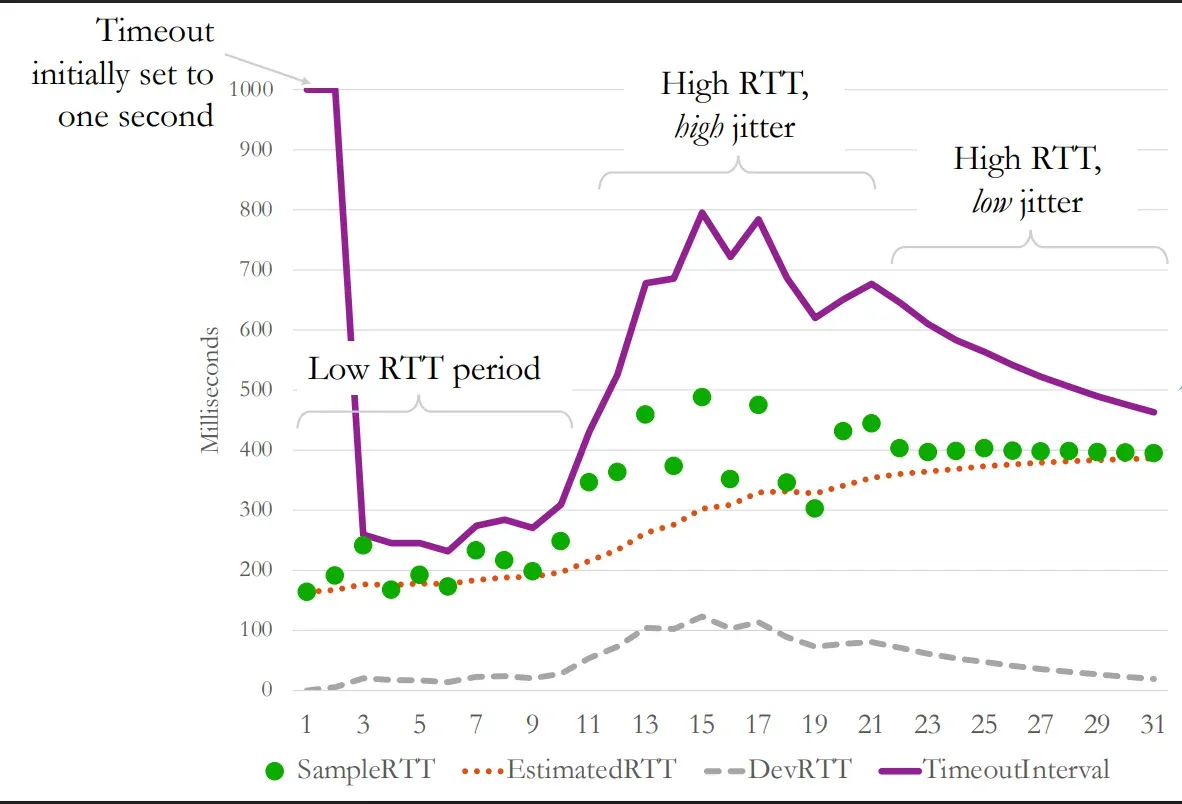
- What should be the ideal value of the timer? because if the timer time is to short you send unwanted packets and if long the response will be slow. hence TCP mesures the round trip time and sets the time or more specifically adapts the timer according to that.
- How is the above mentioned time calculated for the setting the timer? the general formula to estimate that is
NewEstimatedRTT = (1-ɑ)*PreviousEstimatedRTT + ɑ*LatestRTT.
Here ɑ(alpha) is just a constant and is choosed as random but typically a small value - Why have influnce of previousRTT in the formula? this is because if there is a sudden jump in the RTT but only once the value isn’t much deviated but if there are increae in RTT for a significant amount of time then the value will be adjusted slowly.
- After this we set the timeout time to be slightly greter than the NewEstimatedRTT. Why? Because the actual time of response maybe still greter than this calclualted average value.
- Now how much above to set it? this is where comes new thing called jitter. Now what is jitter ? jitter refers to the average variance in RTT.
plaintextDeviationRTT = (1-β)*PreviousDeviationRTT + β*(LatestRTT-NewEstimatedRTTFormPreviousFormula)Typically β is taken around 0.125.
- Final TimeoutIntervalFormula
plaintextTimeoutInterval = NewEstimatedRTT + 4*DeviationRTT- Intitially some value is taken like 1 second when we do not have any value form network.
- This allows us to adapt to changes in connection in realtime for over a very long open connection like watching a movie.
- TCP specification generally receommends that the the receiver waits before sending an acknwladgement as generally the applications send data hence the acknowladgement will be sent along with it automatically. This helps to reduce the load on the trafic. This is called delayed acknowladgement.
Different Events cases sumamry#
| Event at Receiver | TCP Action Taken | Example Scenario |
|---|---|---|
| Arrival of in-order segment with expected seq #. All data up to expected seq # already ACK’ed. | Delayed ACK. Wait up to 500ms for next segment. If no next segment, send ACK. | A web server sends a 1200-byte HTML file to a browser. The browser receives the first 600 bytes (Seq=79, Len=600). Since the browser has nothing to send back immediately, it starts a timer instead of sending an ACK right away. |
| Arrival of in-order segment with expected seq #. One other segment has ACK pending. | Immediately send a single cumulative ACK, ACK’ing both in-order segments. | Before the browser’s delay timer expires, it receives the second 600 bytes of the file (Seq=679, Len=600). The browser now immediately sends a single ACK=1279, acknowledging the receipt of all 1200 bytes. |
| Arrival of out-of-order segment (with higher-than-expect seq #). In other words, a gap was detected. | Immediately send duplicate ACK, indicating seq. # of next expected byte. | A server sends segment A (Seq=1000) and then segment B (Seq=2000). Due to network conditions, the browser receives segment B first. The browser, expecting Seq=1000, immediately sends a duplicate ACK=1000 to signal that it’s still waiting for that specific segment. |
| Arrival of segment that partially or completely fills gap. | Immediately send ACK if segment starts at beginning of gap. | The browser, having received segment B (Seq=2000) and sent a duplicate ACK=1000, now finally receives the missing segment A (Seq=1000). Because this segment fills the gap, the browser immediately sends a new cumulative ACK=3000. |
TCP fast retransmit#
If ever there is a scenario that there are 3 or more than 3 dubplicate acknwladgements are recieved for a lost packet case which is case 3rd in above table then the sender immediately feels that something is wrong and dosen’t wait for the timer to expire but immediately sends the lost packet. More about this here ↗.
TCP flow and congestion control#
- Peak throughput is proportional to the window size and inversly to the round trip time.
- Controlling sender’s window size to prevent packet loss.
- FLow Control -> prevent receiver’s receive buffer overflow. The simple TCP header called receive window is used to keep track of how many new bytes of data can the receiver get.
- congestion control -> prevent overflow of router’s packet queues and network.Tracking this is a lot more complex process. more on this later.
TCP connection setup - three way handshake#
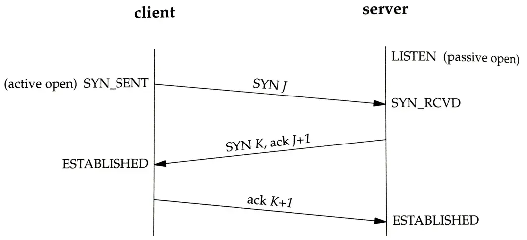
- SYN - Initiatior sends its parameters.
- SYN-ACK - Listner sends its acknowladgements including its own parameters. +1 is done
- ACK - Initiatior acknowladages or possibly share some data also if needed. +1 is done
Congestion control in TCP#
- why is congestion control difficult?
- When network is congested as router queues are full packets can be dropped, or long queues can also lead to expired timers. These lead to inefficency.
- TCP does end to end congestion control.
- Sender tries to estimate a congestion window(cwnd) which is number of packets that can be safely sent without causing congestion.
- number of in-flight packets <= MIN(congestion window,recieve window)
TCP “RENO”#
- it has three phases
- Slow start - initially no idea about the capacity and every RTT the amount of data sent is doubled until we have reached a congestion.
- Congestion Avoidance - we drop down to half the maximum and and then linearly the sending speed is incresed. this is again done until we face a congestion.
- Fast recovery - getting acknowladgements then continue increasing it until we stop recieving acknowladgements then repeat form congestion avoidancec phase.
- Problems with TCP reno
- Even though the increase is exponential for very high throughput connection like optical fiber cables witch 10Gbs speeds even starting form something like 1500 bits/sec will take about 3.5 hrs of time and trillions of packets being already being sent at very low speeds. To overcome this we use higer exponential increase times such as cubinc increase.
- When RENO reaches the full capacity the queue start to fill up before dropping down and in some cases even resulting to full queues. This is not good as this results in what we are trying to control congestion along with increase in RTT.
- Increased Latency: Full queues lead to higher Round-Trip Times (RTTs) before congestion is detected.
Vegas congestion control#
Developed in the 1990s at the University of Arizona, Vegas was the first major delay-based congestion control algorithm.These algorithms help us to counter full queues problem that the RENO had previously.
- Delay-Based Detection: Vegas monitors RTT variations rather than waiting for packet drops.
- Calculates expected throughput: cwnd / BaseRTT (where BaseRTT is the minimum observed RTT)
- Early Congestion Detection: By detecting increasing RTTs before packet loss occurs, Vegas can adjust sending rate proactively.
- advantages
- Stable Throughput: Maintains consistent sending rates with fewer oscillations
- Lower Queuing Delay: Prevents large queue buildup at routers
- Higher Network Utilization: Can achieve better throughput with lower packet loss
- Reduced Retransmissions: Proactive nature results in fewer lost packets
- Disadvantages
- Unfairness with RENO: When competing with loss-based algorithms, Vegas backs off too early
BBR (Bottleneck Bandwidth and Round-trip propagation time)#
Developed by Google in 2016, BBR represents a more sophisticated model-based approach to congestion control.
-
Core Mechanism
-
Explicit Modeling: BBR builds an explicit model of the network by estimating two key parameters:
-
Bottleneck Bandwidth (BtlBw): Maximum data delivery rate
-
Round-trip propagation time (RTprop): Minimum RTT when queues are empty
-
Operating Point: BBR aims to operate at the optimal point where:
Sending rate equals the bottleneck bandwidth Amount of in-flight data equals BDP (Bandwidth-Delay Product = BtlBw × RTprop) State Machine: BBR cycles through different states:
Startup: Exponential growth to quickly discover bandwidth (similar to RENO’s slow start) Drain: Reduces in-flight data to drain queues ProbeBW: Periodic bandwidth probing to detect changes ProbeRTT: Periodically reduces in-flight data to measure RTprop accurately Pacing: BBR uses packet pacing to evenly space packet transmissions rather than sending them in bursts.
-
-
BBR Advantages
- High Utilization with Low Delay: Achieves near-optimal throughput without filling queues
- Resilience to Random Loss: Performance doesn’t degrade with non-congestion packet loss
- Better Performance on High BDP Networks: Excels on satellite, cellular, and high-speed networks
- Fairness Across Different RTTs: Less biased against long-RTT connections than RENO
-
BBR Limitations
-
Implementation Complexity: More complex to implement than loss-based algorithms
-
Measurement Precision: Requires accurate timing mechanisms
-
Buffer Issues: Can still cause buffer overflow with extremely shallow buffers
-
Fairness Concerns: Early versions had fairness issues when competing with other algorithms
-
Nagle’s algorithm#
- Each TCP packet has almost 40 bytes of header overhead.
- This is a special algorithm that combines all those common headers for the shorter message if the message to be sent is not the first message.
- This algorithm is a bit slow as it instructts that the messages shotld be heald for a small period before sendig them.
SOCKET DIFFERENT CONFIGURATIONS#
- TCP_NODELAY => This option disables Nagel’s algorithm. Every segment written is sent immediately if space is there in window size.
- TCP_NOPUSH => It is a more aggressive version of the Nagle algorithm. It will wait until send buffer is full before sending the segment.
- PSH bit => this bit can be set by sender to indiacte the receiving device that the data when ready to be immediately sent insead of buffring.
TCP keepalive header#
-
if there is no data to be sent a empty data segment is sent called keepalive in frequency of around 1 time/min so that the connection is not terminated.
-
it also forces the NAT routers to keep their port-mappings alive for that ip.
IP/Forwarding#
what do routers do ? how do routers know where to send which packet? how do we navigate the internet??… everything answeerd.
This is layer third of the several layers the IP packet layer.
IP(Internet protocol) delivers packets (datagrams). MTU (Maximum transmission Unit) limits the datagram size.
Routing is the proecess of guiding packets to their destination. It operates in 2 parts.
- Control Plane
- Data Plane
Each router is unknown of the end to end behaviour of the network but only knows to how to forward the packets to its neighbourhood.
IPv4 addressing#
- Interface is defined as every device connected to network and havingg an ip address.
- the ipv4 addressess consist of 4 numbrs form 0-255 seprated with a period(.) and is 32 bits long in version 4.
- there is an ip address for each interface that is communicating to network on the host.
MAC address (Media Access Control)#
- these are used during local communication.
- These are hard coded form the factory and cannot be changed.
- 48-bit Identifier: Typically represented as six groups of two hexadecimal digits (e.g., 00:1A:2B:3C:4D:5E)
- Manufacturer Assigned: The first 24 bits (OUI - Organizationally Unique Identifier) identify the manufacturer
- Physical Layer Addressing: Used for device-to-device communication within the same network segment
- Flat Addressing: Unlike hierarchical IP addresses, MAC addresses have no inherent routing structure
- Types of MAC Addresses
- Unicast: Identifies a specific network interface (most common)
- Multicast: Identifies a group of devices (starts with 01:00:5E for IPv4 multicast)
- Broadcast: Sent to all devices on a network segment (FF:FF:FF:FF:FF:FF)
- Bit 7 of the first byte: 0 for unicast, 1 for multicast
- Bit 8 of the first byte: 0 for globally unique, 1 for locally administered
IP subnets#
- Subnets are chunks of IP addresses in the network that can communicate directly without travelling through the router.
- Routers can send packets betweeent the subnets.
- Subnet mask indicates the bit position where subnet is split. the x subnet mask means the number of bits that are common and after that the 32-x bits are for the differnt machine.
- To understand why 255.255.255.240 is a subnet mask:
- Converting to binary:
11111111.11111111.11111111.11110000. The 1 bits represent the network portion, The 0 bits represent the host portion. - CIDR Notation: This subnet mask has 28 consecutive 1 bits, so it’s a /28 in CIDR notation.
- With 4 host bits (the zeros), this subnet provides 2⁴ = 16 addresses.
- Usable addresses: 14 (excluding network address and broadcast address).
- If applied to network 192.168.1.16:
- Network address: 192.168.1.16
- Broadcast address: 192.168.1.31
- Usable host addresses: 192.168.1.17 through 192.168.1.30
- When a device wants to send data, it performs a bitwise AND operation between the destination IP and subnet mask. If the result matches its own network, communication occurs directly.
- Converting to binary:
Address Resolution Protocol (ARP)#
- Bridges the gap between Layer 3 (IP) and Layer 2 (MAC)
- Maps IP addresses to MAC addresses on a local network
- Devices maintain an ARP cache of recently mapped addresses
- Example: “Who has IP 192.168.1.5? Tell 192.168.1.1” → “192.168.1.5 is at 00:1A:2B:3C:4D:5E”
- CIDR notation (123.100.16.0/28) specifies a range of addresses
- Used both for specifying subnets and for routing rules.
- /28 or 255.255.255.240 is called a subnet mask.
NAT (Network address translation)#
IPv4 addresses are in short supply (4 billion). ISP often will give you just one address, so how to connect multiple devices?
also called layer 4 load balancer.
below is a sample NAT translation
[Client]                    [NAT Router]                  [Internet Server]
192.168.1.10:4321           Public IP: 203.0.113.5        74.125.193.100:80
     |                              |                            |
     |  Request                     |                            |
     |----------------------------->|                            |
     | Src: 192.168.1.10:4321       | Src: 203.0.113.5:12345     |
     | Dst: 74.125.193.100:80       | Dst: 74.125.193.100:80     |
     |                              |--------------------------->|
     |                              |                            |
     |                              |        Response            |
     |                              |<---------------------------|
     |        Response              | Src: 74.125.193.100:80     |
     |<-----------------------------|  Dst: 203.0.113.5:12345    |
     | Src: 74.125.193.100:80       |                            |
     | Dst: 192.168.1.10:4321       |                            |
DHCP (Dynamic Host Configuration Protocol)#
DHCP is a network management protocol that automatically assigns IP addresses and other network configuration parameters to devices on a network.
The steps for dhcp are:-
- DHCP Discovery (DHCPDISCOVER) :- Client broadcasts a request for network configuration. Message uses source IP 0.0.0.0 and destination 255.255.255.255 (broadcast). Contains client’s MAC address as identifier
- DHCP Offer (DHCPOFFER) :- DHCP server responds with available IP address and configuration. Message includes lease duration and server identifier. Multiple servers may respond with different offers.
- DHCP Request (DHCPREQUEST) :- Client broadcasts which offer it accepts.Broadcasting allows other DHCP servers to withdraw their offers. Includes the server identifier of the chosen server.
- DHCP Acknowledgment (DHCPACK) :- Selected server confirms configuration parameters.Officially assigns IP address to client. Provides all network parameters. Sets lease duration.
below is a dhcp packet structure
 0                   1                   2                   3
 0 1 2 3 4 5 6 7 8 9 0 1 2 3 4 5 6 7 8 9 0 1 2 3 4 5 6 7 8 9 0 1
+-+-+-+-+-+-+-+-+-+-+-+-+-+-+-+-+-+-+-+-+-+-+-+-+-+-+-+-+-+-+-+-+
|     op (1)    |   htype (1)   |   hlen (1)    |   hops (1)    |
+-+-+-+-+-+-+-+-+-+-+-+-+-+-+-+-+-+-+-+-+-+-+-+-+-+-+-+-+-+-+-+-+
|                            xid (4)                            |
+-+-+-+-+-+-+-+-+-+-+-+-+-+-+-+-+-+-+-+-+-+-+-+-+-+-+-+-+-+-+-+-+
|           secs (2)            |           flags (2)           |
+-+-+-+-+-+-+-+-+-+-+-+-+-+-+-+-+-+-+-+-+-+-+-+-+-+-+-+-+-+-+-+-+
|                          ciaddr (4)                           |
+-+-+-+-+-+-+-+-+-+-+-+-+-+-+-+-+-+-+-+-+-+-+-+-+-+-+-+-+-+-+-+-+
|                          yiaddr (4)                           |
+-+-+-+-+-+-+-+-+-+-+-+-+-+-+-+-+-+-+-+-+-+-+-+-+-+-+-+-+-+-+-+-+
|                          siaddr (4)                           |
+-+-+-+-+-+-+-+-+-+-+-+-+-+-+-+-+-+-+-+-+-+-+-+-+-+-+-+-+-+-+-+-+
|                          giaddr (4)                           |
+-+-+-+-+-+-+-+-+-+-+-+-+-+-+-+-+-+-+-+-+-+-+-+-+-+-+-+-+-+-+-+-+
|                          chaddr (16)                          |
+-+-+-+-+-+-+-+-+-+-+-+-+-+-+-+-+-+-+-+-+-+-+-+-+-+-+-+-+-+-+-+-+
|                          sname (64)                           |
+-+-+-+-+-+-+-+-+-+-+-+-+-+-+-+-+-+-+-+-+-+-+-+-+-+-+-+-+-+-+-+-+
|                          file (128)                           |
+-+-+-+-+-+-+-+-+-+-+-+-+-+-+-+-+-+-+-+-+-+-+-+-+-+-+-+-+-+-+-+-+
|                          options (variable)                   |
+-+-+-+-+-+-+-+-+-+-+-+-+-+-+-+-+-+-+-+-+-+-+-+-+-+-+-+-+-+-+-+-+DHCP Options
- Option 1: Subnet Mask
- Option 3: Router (Default Gateway)
- Option 6: DNS Servers
- Option 15: Domain Name
- Option 51: IP Address Lease Time
- Option 53: DHCP Message Type
- Option 54: DHCP Server Identifier
- Option 58: Renewal Time Value (T1)
- Option 59: Rebinding Time Value (T2)
- Option 82: Relay Agent Information (used for DHCP snooping)
DHCP Implementation
- server side :-
- Microsoft DHCP Server: Windows Server
- ISC DHCP: Common on Linux/Unix
- Dnsmasq: Lightweight option for small networks
- Router DHCP: Built into most home/SMB routers
Routing inside routers and algotithms#
Routers use forwarding tables to direct IP packets to the next hop
below is an example
| Destination | Subnet Mask | Next Hop | Interface | Metric |
|---|---|---|---|---|
| 0.0.0.0 | 0.0.0.0 | 203.0.113.1 | eth0 | 1 (Default route) |
| 192.168.1.0 | 255.255.255.0 | Directly Connected | eth1 | 0 (Local subnet) |
| 192.168.2.0 | 255.255.255.0 | Directly Connected | eth2 | 0 (Local subnet) |
| 10.10.0.0 | 255.255.0.0 | 192.168.1.20 | eth1 | 10 (Internal network) |
| 172.16.50.0 | 255.255.255.0 | 192.168.2.100 | eth2 | 5 (Branch office) |
| 203.0.113.0 | 255.255.255.0 | Directly Connected | eth0 | 0 (ISP network) |
| 8.8.8.0 | 255.255.255.0 | 203.0.113.1 | eth0 | 15 (External specific route) |
How routers use this table
- When a packet arrives, the router extracts the destination IP address
- The router compares this address with each entry in the forwarding table
- It performs a “longest prefix match” - finds the entry with the most specific (longest) matching network prefix.
- The packet is then forwarded to the next-hop IP or directly to the interface specified in the matching entry.
- If no match is found, the default route (0.0.0.0/0) is used
Mordern routers architecture#
INPUT Ports#
- Each input port has a copy of the routing table decidied by the control plane using algorithms such as BGP. Using these table the input ports figure out where to send the data to. below is a simplified structure of these.
Switching Fabric#
- This is the connection between input and output ports.
- Switching Rate -> The theoritical maximum rate of data transfer from all input to output ports. Ideally it should be very fast and near about (number of inputs * average input line rate)
- There are two types of switching fabric :-
- Bus -> This is the simplest design and can only be used by one input port at a time. This is genrally used in commercial routers. A longer queue is often maintained.
- Crossbar -> This is a much complex design and can allow multiple inputs to switch at a time by switching connections appropriately. This requires m*n points or switches for m input and n output ports. It is used in the core server routers.
OUTPUT Ports#
- The data is sent out from this to required destination.
- Buffering is required because switch fabric may be faster than physical output link and hence packets gets buffered.
- A queued packet can be scheduled if desired on basis of priority.
- Give higher priority to certain types of packets based on origin/ip/destination etc.
- Net Neutrality is the policy debate about weather the ISPs can do this or not.
Weighted Fair Queuing (WFQ)#
- Traffic is divided into separate flows (based on source/destination IP, ports, protocol, etc.)
- Flows receive different weights based on priority or requirements
- Bandwidth is allocated proportionally to weights
- WFQ operates on a theoretical model called Generalized Processor Sharing (GPS)
- WFQ simulates a system that could serve one bit from each flow in round-robin fashion (though real packets are indivisible)
- Each packet is assigned a “virtual finish time” - when it would complete service in the theoretical bit-by-bit system.
- The packet with the smallest virtual finish time is selected for transmission.
- Some varients include :- Class-Based WFQ (CBWFQ),Low Latency Queuing (LLQ),Deficit WFQ (DWFQ).
Centralized vs Distributed algorithms#
-
Centralized/global routing
- Algorithm has full knowledge of the entire network.
- Makes decisions that affect all routers
- In routing, we call these link state algorithms.
- Used within an organization (autonomous system) (eg., OSPF)
- Dijkstra’s Algorithm is a fast centralized algorithm where routers initially flood/broadcast local link information to entire network and them each router solves the shortest path from itself to other routers.
-
distributed/local routing
- Each router must decide its own routing table using local observations.
- Operates iteratively.
- Routers continually share information with neighbors
- Global information is gradually propagated across the network.
- Used within and between autonomous systems (eg., RIP & BGP, respectively)
- Distance Vector (DV) algorithm is a distributed shortest path algorithm where initially, routers only knows distance to neighbors – broadcast to neighbors and when receive a neighbor’s DV, update own DV, & broadcast if DV changed.
-
Interiror gateway protocols (Intra AS-routing)
- Centralized IGP
- Open shortest path first (OSPF)
- Intermediate system to Intermediate System (IS-IS)
- Distributed IGP
- Routing information Protocol
- Enhanced interior gateway routing protocol (EIGRP)
- Centralized IGP
-
Disatnce Vector Algorithm
Below is a sample table
| Destination | Metric | Next Hop | Interface | Timer |
|---|---|---|---|---|
| 192.168.1.0/24 | 0 | Direct | eth0 | - |
| 192.168.2.0/24 | 0 | Direct | eth1 | - |
| 10.0.0.0/16 | 1 | 192.168.2.254 | eth1 | 120s |
| 172.16.0.0/16 | 2 | 192.168.2.254 | eth1 | 120s |
| 172.17.0.0/16 | 3 | 192.168.1.100 | eth0 | 90s |
| 192.168.5.0/24 | 1 | 192.168.1.100 | eth0 | 120s |
| 192.168.6.0/24 | 2 | 192.168.1.100 | eth0 | 120s |
| 203.0.113.0/24 | 1 | 192.168.2.254 | eth1 | 120s |
| 8.8.8.0/24 | 3 | 192.168.2.254 | eth1 | 60s |
| 0.0.0.0/0 | 1 | 192.168.2.254 | eth1 | 120s |
- Destination: Network address with subnet mask
- Metric: Distance to the destination (typically hop count in basic DV algorithms)
- Next Hop: IP address of the next router to forward packets to
- Interface: Local interface to use for forwarding
- Timer: Expiration timer for the route (used to detect stale routes)
- Directly connected networks (metric 0) are 192.168.1.0/24 and 192.168.2.0/24
- Networks with metric 1 are one hop away through adjacent routers
- Networks with metrics 2 and 3 are farther away, reached through intermediate routers
- The default route (0.0.0.0/0) sends any unmatched traffic to 192.168.2.254
- Each network node has its own Distance vector listed as follows <cost,next_hop> to the next destination.
- When a distance vector changes at one node after re-calculation it notifies the other nodes.
- Re-calculation is done when the local link cost changes.
- If a link cost is decreased it is a good news and propogates quickly
- The entire table like above is sent to neighbours and received from them.
Count to infinity problem#
The “Count to Infinity” problem is a fundamental issue in distance vector routing protocols like RIP (Routing Information Protocol) where routers can get stuck in a routing loop, continuously incrementing route metrics toward an unreachable destination.
Router A ---- Router B ---- Router C ---- Network X
- Initial State
- Router C directly connects to Network X (cost 0)
- Router B can reach X via C (cost 1)
- Router A can reach X via B (cost 2)
- When Network X fails
- Router C detects the failure and marks X as unreachable
- Before C informs B, B sends its regular update to A saying X is reachable (cost 1)
- A updates its routing table: X is reachable via B (cost 2)
- B receives C’s update that X is unreachable
- B checks its alternatives and sees A advertising a path to X (cost 2)
- B updates: X is reachable via A (cost 3)
- A receives B’s update and updates: X is reachable via B (cost 4) This cycle continues with metrics incrementing until reaching “infinity”
Solution to count to infinity#
A few solution to above problem are discussed below
- Split Horizon with Poison reverse
- Principle: Actively advertise routes learned from a neighbor back to that neighbor, but with an infinite metric
- Example: B tells A that X is unreachable through B (infinity)
Autonomous Systems#
In reality not all routers are equal due to scaling and administrative purposes. The internet is divided into 100k autonoumous systems having AS numbers given by ICANN.Routers in an AS run one interior-gateway (intra-AS) routing protocol. Border Gateway Protocol (BGP) is used by all border gateways to route traffic between AS’s.
OSPF (Open Shortest Path First)#
OSPF is a widely used link-state routing protocol designed for IP networks. As an Interior Gateway Protocol (IGP), it operates within a single Autonomous System (AS) and is one of the most popular protocols for large enterprise networks.
- While distance vector protocols (like RIP) share entire routing tables with neighbors, OSPF shares information about the state of directly connected links
- Each OSPF router maintains an identical database that represents the entire network topology
- Each router independently computes optimal routes using Dijkstra’s Shortest Path First (SPF) algorithm
- Messages are authenticated to prevent malicious tampering.
- Multiple same-cost paths are allowed.
- Links can have different costs for different types of traffic.
- Hierarchical OSPF can be used in large AS’s.
- Generally, an AS can be divided into multiple private AS’s internally, but look like one AS to outside Internet.
                      | boundary router
                      ▼
          ┌───────────────────────┐
          │                       │
    ┌─────┴─────┐           ┌─────┴─────┐
    │           │           │           │
    ▼           ▼           ▼           ▼
┌─────────┐     │      ┌─────────┐      │
│backbone │◄────┴─────►│backbone │◄─────┘
│ router  │            │ router  │
└────┬────┘            └────┬────┘
     │                      │
     │        backbone      │
     │        (Area 0)      │
     │                      │
┌────▼────┐            ┌────▼────┐
│  area   │            │  area   │
│ border  │            │ border  │
│ router  │            │ router  │
└────┬────┘            └────┬────┘
     │                      │
     ▼                      ▼
  ┌─────┐                ┌─────┐
  │     │                │     │
┌─▼─┐ ┌─▼─┐            ┌─▼─┐ ┌─▼─┐
│   │ │   │            │   │ │   │
▼   ▼ ▼   ▼            ▼   ▼ ▼   ▼
┌───┐ ┌───┐            ┌───┐ ┌───┐
│   │ │   │            │   │ │   │
└───┘ └───┘            └───┘ └───┘
internal routers      internal routers
area 1 area 2 area 3Border gateway protocol (Inter-AS routing)#
- BGP is the Internet-standard routing protocol for connecting AS
- eBGP: allows neighboring AS’s to share their subnet reachability information: “I can reach 3.2.4.0/24 in 4 hops”
- iBGP: propagates reachability information to all AS-internal routers.
- below is a sample BGP advertisement
UPDATE MESSAGE
+----------------------------------------------------+
| Prefix          | 192.0.2.0/24                     |
| NEXT_HOP        | 203.0.113.1                      |
| AS_PATH         | 65001 64512 64513                |
| ORIGIN          | IGP                              |
| LOCAL_PREF      | 100                              |
| MED             | 10                               |
| COMMUNITY       | 65001:200, 65001:3000, no-export |
+----------------------------------------------------+

Info:-

ORIGIN: IGP
Indicates how the route was originally learned.

LOCAL_PREF: 100
Used within an AS to prefer one exit point over another
Higher values are preferred
Not passed to external BGP peers

MED: 10
Multi-Exit Discriminator - suggests to neighboring ASes which entry point to use
Lower values are preferred

COMMUNITY: 65001:200, 65001:3000, no-export
Tags attached to routes for implementing routing policies
"no-export" means this route should not be advertised outside the receiving ASBGP Session#
- two BGP routers (“peers”) exchange BGP messages
- advertise paths to different destination network prefixes (network prefixes are the nodes/endpoints in this shortest-path problem).
- exchanged over semi-permanent TCP connections
- AS can aggregate prefixes in its advertisement. (ex:- 20.1.0.0/24 + 20.1.1.0/2 + 20.1.2.0/24 + 20.1.3.0/24 = 20.1.0.0/22)
- AS-PATH: AS numbers through which the advertisement has passed. Indicates the AS-path that will be followed to reach the prefix.
- NEXT-HOP: IP address of the router beginning the AS-PATH.
- Prefix: Act like final destination.
- In above example using the 3 fields as-path,next-hop,prefix we can say that “You can send traffic to 192.0.2.0/24 through my router 203.0.113.1, and it will travel through three AS’s before arriving.”
- BGP advertise the full AS_PATH instead of just the path length because it allows to prevent loops. Like example if I am AS0 and I receive a route with path [2, 4, 0, 5], I should not use it.
BGP Route Selection in practice#
- AS policy determines local preference for various routes. (A hard-coded preference based on financial cost, agreements, etc.)
- Among routes with the highest local preference, choose route with shortest AS-PATH. (DV algorithm.)
- If multiple options remain, use hot-potato routing, that is, choose the route whose NEXT-HOP is closest. • This considers the within-AS distance using an IGP such as OSPF.
- If multiple options still exist, use a random tie-breaker (eg., BGP router id)
Types of Autonomous Systems#
- Stub connects to just one other AS
- Transitconnects to multiple AS’s and routes between them. example is tier 1 ISP.
- Multihomedconnects to multiple other AS’s, but do not route between.
Packet delivery#
Types of delivery#
- Unicast :- one to one node
- Anycast :- to one of many possible nodes
- Broadcast :- to all the nodes
- Multicast :- to set of nodes
- Geocast :- to many or one node of a specific location
IPv4 anycast hack#
The single IP address 8.8.8.8 maps to may different machines across the world, using a hack called IPv4 anycast.
Broadcast#
Internet generally dosen’t support broadcast as no information is relevant enough for whole internet. Some private networks use broadcast. But how do we broadcast without putting excess load on the network.
Ans) We use a MST(Minimum spanning tree) which allows the message to be received by all the nodes. But this requires all nodes to have a complete knowladge of the network and every node must calculate the same MST.
Summary#
Key Protocols by Layer
- Application Layer (Layer 7)
- HTTP/HTTPS: Web browsing, APIs
- SMTP: Email transmission
- DNS: Domain name resolution
- DHCP: Dynamic host configuration
- FTP: File transfer
- Transport Layer (Layer 4)
- TCP: Connection-oriented, reliable delivery
- Three-way handshake
- Flow control (receive window)
- Congestion control (RENO, Vegas, BBR)
- Sequence and acknowledgment numbers
- UDP: Connectionless, minimal overhead
- No reliability or ordering guarantees
- Lower latency
- Network Layer (Layer 3)
IP: Logical addressing and routing
- ICMP: Error reporting and diagnostics
- OSPF: Link-state routing within AS
- BGP: Path-vector routing between AS
- NAT: Address translation for private networks
- Data Link Layer (Layer 2)
- Ethernet: Local area networking
- ARP: Maps IP addresses to MAC addresses
- PPP: Point-to-point connections
+-------+------------+-----------------------------+--------------------------------+----------------+-----------------------------+
| Layer | Name       | Key Functions              | Protocols                      | Addressing     | Example Devices/Technologies |
+-------+------------+-----------------------------+--------------------------------+----------------+-----------------------------+
| 7     | Application| • End-user services         | • HTTP/HTTPS                   | URLs, Domain   | Web browsers, Email clients |
|       |            | • Data generation           | • SMTP                         | Names          |                             |
|       |            | • Service-specific functions| • DNS                          |                |                             |
|       |            |                             | • FTP                          |                |                             |
|       |            |                             | • SSH                          |                |                             |
|       |            |                             | • BitTorrent                   |                |                             |
+-------+------------+-----------------------------+--------------------------------+----------------+-----------------------------+
| 6     | Presentation| • Data format translation   | • SSL/TLS                      | N/A            | Encoding converters         |
|       |            | • Encryption/Decryption     | • MIME                         |                |                             |
|       |            | • Compression               | • JPEG, PNG                    |                |                             |
+-------+------------+-----------------------------+--------------------------------+----------------+-----------------------------+
| 5     | Session    | • Session establishment     | • NetBIOS                      | Session IDs    | APIs, Remote procedure calls|
|       |            | • Session management        | • RPC                          |                |                             |
|       |            | • Dialog control            |                                |                |                             |
+-------+------------+-----------------------------+--------------------------------+----------------+-----------------------------+
| 4     | Transport  | • End-to-end connections    | • TCP (Connection-oriented)    | Ports (0-65535)| Load balancers, Firewalls   |
|       |            | • Reliability               | • UDP (Connectionless)         |                |                             |
|       |            | • Flow control              | • QUIC                         |                |                             |
|       |            | • Congestion control        |                                |                |                             |
+-------+------------+-----------------------------+--------------------------------+----------------+-----------------------------+
| 3     | Network    | • Logical addressing        | • IP (IPv4, IPv6)              | IP addresses   | Routers                     |
|       |            | • Path determination        | • OSPF                         |                |                             |
|       |            | • Packet forwarding         | • BGP                          |                |                             |
|       |            | • Subnetting                | • RIP                          |                |                             |
|       |            |                             | • ICMP                         |                |                             |
|       |            |                             | • NAT                          |                |                             |
+-------+------------+-----------------------------+--------------------------------+----------------+-----------------------------+
| 2     | Data Link  | • Physical addressing       | • Ethernet                     | MAC addresses  | Switches, Network adapters  |
|       |            | • Media access control      | • ARP                          |                |                             |
|       |            | • Error detection           | • PPP                          |                |                             |
|       |            |                             | • VLAN                         |                |                             |
+-------+------------+-----------------------------+--------------------------------+----------------+-----------------------------+
| 1     | Physical   | • Raw bit transmission      | • Ethernet physical            | None           | Cables, Hubs, Repeaters     |
|       |            | • Physical medium specs     | • USB                          |                |                             |
|       |            | • Signal encoding           | • Bluetooth                    |                |                             |
|       |            |                             | • DSL                          |                |                             |
+-------+------------+-----------------------------+--------------------------------+----------------+-----------------------------+